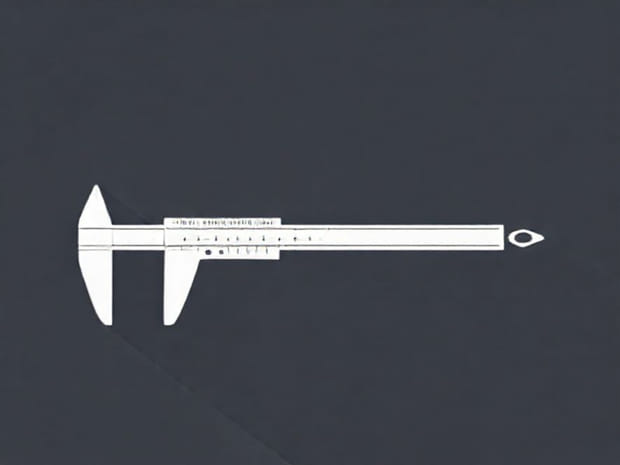
Diagram Of Vernier Caliper
The vernier caliper is a precision measuring instrument used to measure internal and external dimensions as well as depths with high accuracy. It is commonly used in mechanical engineering, metalworking, woodworking, and laboratory applications. The diagram of a vernier caliper is essential for understanding its structure, parts, and how it functions. By analyzing the diagram, students, engineers, and technicians can learn how to read measurements correctly and use the caliper effectively. This topic explores the diagram of a vernier caliper, explaining each component, its function, and tips for accurate measurement.
Overview of a Vernier Caliper
A vernier caliper consists of a main scale and a sliding vernier scale that allows users to measure dimensions with precision. It combines simplicity with high accuracy, often capable of measuring to the nearest 0.02 mm or 0.001 inches. The diagram of a vernier caliper provides a clear visual representation of its components, which include jaws, a beam, a depth probe, and locking mechanisms. Understanding the layout and parts of the caliper is crucial for correct usage and accurate readings.
Main Components in the Diagram
The diagram of a vernier caliper typically highlights several key components, each serving a specific function in measurement. These components include
- Main ScaleThe fixed scale engraved on the body of the caliper, usually in millimeters and inches, providing the base measurement.
- Vernier ScaleA smaller, movable scale that slides along the main scale, allowing precise readings between the main scale markings.
- Fixed JawThe stationary jaw attached to the main scale that forms one side of the object being measured.
- Sliding JawThe movable jaw attached to the vernier scale that moves along the main scale to grip the object for measurement.
- Depth Rod or ProbeA thin rod extending from the end of the caliper for measuring depths of holes, slots, or recesses.
- Locking ScrewA screw used to fix the sliding jaw in place to maintain a measurement.
- Thumb Screw or SliderA knob or mechanism that allows smooth movement of the sliding jaw along the main scale.
Reading the Diagram of a Vernier Caliper
Understanding the diagram helps in reading measurements accurately. The main scale provides the primary measurement, while the vernier scale allows for fine readings. When the zero of the vernier scale aligns with the main scale, the reading is simple, but for precise measurements, users observe the point where lines on the vernier scale coincide with lines on the main scale. This method increases accuracy and reduces human error in measurements.
Steps for Using the Diagram to Measure
- Identify the part of the object to be measured, whether it is external, internal, or depth measurement.
- Place the object between the fixed and sliding jaws, or position the depth probe into the hole.
- Adjust the sliding jaw until it fits snugly against the object or reaches the desired depth.
- Read the main scale measurement just before the zero of the vernier scale.
- Identify the vernier scale line that aligns perfectly with a main scale line and add this to the main scale reading for precise measurement.
Applications of the Vernier Caliper
The diagram of a vernier caliper is not just educational; it provides practical insights into its applications. Vernier calipers are widely used in
Mechanical Engineering
Engineers use vernier calipers to measure components such as shafts, holes, and mechanical parts to ensure precision and maintain tolerances. Accurate measurements are critical for assembly, performance, and quality control.
Manufacturing and Metalworking
In metalworking, vernier calipers measure thickness, diameters, and depths of metal sheets or machined parts. The diagram helps workers identify correct jaw placement and probe usage for accurate measurement.
Laboratory and Scientific Use
In laboratories, vernier calipers measure small objects, samples, and experimental apparatus. The diagram provides a visual guide to avoid misuse and obtain reliable data.
Woodworking and Craftsmanship
Woodworkers use vernier calipers to measure cuts, grooves, and spacing precisely. Understanding the diagram ensures correct measurement techniques and reduces material waste.
Advantages of Understanding the Diagram
Studying the diagram of a vernier caliper provides several advantages
- Improves measurement accuracy by understanding each component’s function.
- Helps prevent damage to the instrument by using the jaws and probe correctly.
- Enhances learning for students and beginners in electronics, engineering, and mechanics.
- Facilitates troubleshooting and maintenance by identifying key parts like the locking screw and sliding mechanism.
Tips for Effective Use
- Always keep the caliper clean and free from debris to avoid measurement errors.
- Use the locking screw to fix the sliding jaw during reading for stability.
- Practice reading the vernier scale regularly to increase speed and accuracy.
- Ensure proper alignment of the jaws or depth probe with the object for reliable measurements.
The diagram of a vernier caliper is an essential tool for understanding its structure, components, and proper usage. It highlights the main scale, vernier scale, fixed and sliding jaws, depth probe, locking screw, and other critical parts. By studying the diagram, users can perform precise measurements of external and internal dimensions, as well as depths, across a wide range of applications in engineering, metalworking, laboratories, and woodworking. Mastery of the diagram not only enhances measurement accuracy but also improves the handling and longevity of the instrument. Familiarity with the parts and their functions is key for anyone looking to utilize vernier calipers effectively in their work or studies.